The Kingpins : Stub Axles and Yokes
Many people may be confused by this terminology, however correct and important to get right.
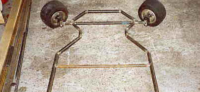
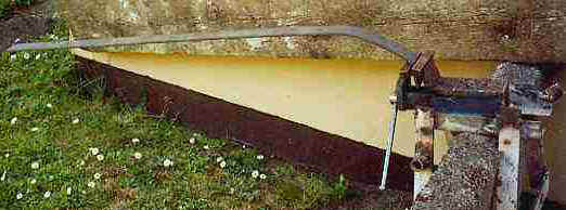
Basically all that is meant is that the stub axle onto the end of which is attached the front wheels pivots via the kingpin connecting to the kart via the yoke. You can see from the picture below what we are trying to achieve.
Things however get a bit more complicated in the following section:
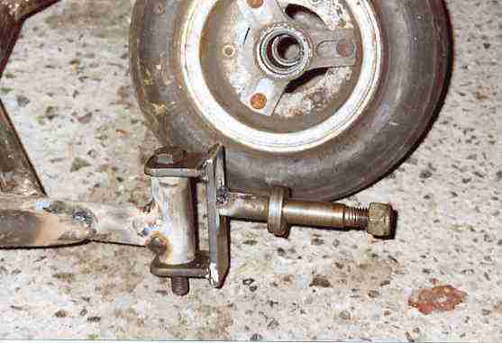
To make the kart handle properly both on corners and on straights the camber and castor angles need to be considered and applied practically to achieve better performance. All angles are taken and measured from the KINGPIN and the flat ground level (make sure chassis is flat and level on the ground). You can see the kingpin in the above photo (Basically a 4""/ 100mm 13mm high tensile steel bolt).
There are two parts to the steering system: 1. the 25mm O.D. cylindrical mild steel pipe (internal Dia. 13mm)
2. the yoke (n shaped object on it's side).
---------------------------------------------------------------------------------------------------------------
1. The 25mm O.D. cylindrical mild steel pipe.
This part is welded to the chassis and it is here where the castor and camber angles are integrated. You can see from the photo directly below how the chassis is mouthed specially to accommodate this cylindrical pipe. To make life easier I made a jig, - I got an old 13mm bolt, attached it to a flat piece of metal and adjusted this bolt until the required angles were achieved. Then I put the cylindrical pipe onto this jig, placed it up to the chassis, cut out the mouthed piece and then welded this cylindrical piece to the chassis.
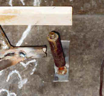
Bear with me for a minute and I will try and explain the angles.
Castor Angle: 20 degrees. This is where the kingpin/ bolt is pointing down forwards towards the front of the kart and the top of the bolt is facing back towards the rear of the kart. You can slightly see this angle in the above photo.
Camber Angle: 12 degrees. This is where the kingpin/ bolt is pointing down away to either side of the kart. You can see this better on the photo below.
--------------------------------------------------------------------------------------------------------------
2. The yoke (n shaped object on it's side).
You can easily see this "n" shaped part in the above photo. I initially though I could get this "n" shape by bending is complete from a piece of flat bar, to no success though as you can see from the photo below.
So as a result I had to resort to patiently cutting out each of the pieces and carefully welding them together taking care not to leave any weak areas. From the photo below you can see all the necessary measurements.
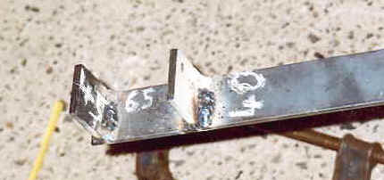
The three measurements in the above photo are: 45mm, 65mm and 40mm. The material is 6mm thick flat bar 40 mm wide. A 300mm long piece will suffice for this. Remember two pieces will have to be made, one for either side. A 13mm hole will have to be made in these parts to accommodate the kingpin.
Remember to make sure all welds are double checked and that enough weld is used, making sure it penetrates into the two adjoining pieces !!!!!
If you are having any trouble getting your head around any of the castor and camber angles etc. etc. firstly go to the following link: Free Kart Plans - Stub Axles. If you are still puzzled e-mail me: steviewdr@hotmail.com
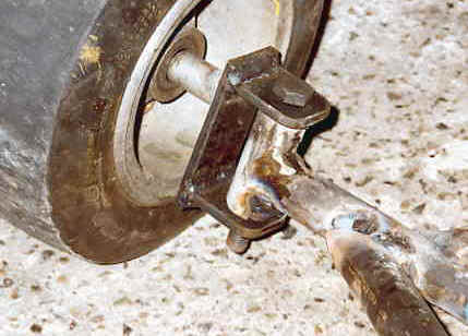
Basically if everything goes to plan you should be at the stage as seen in the photo below, after having welded the stub axles to the "n" shaped part. The wheel should pivot/ rotate freely and should be greased up.