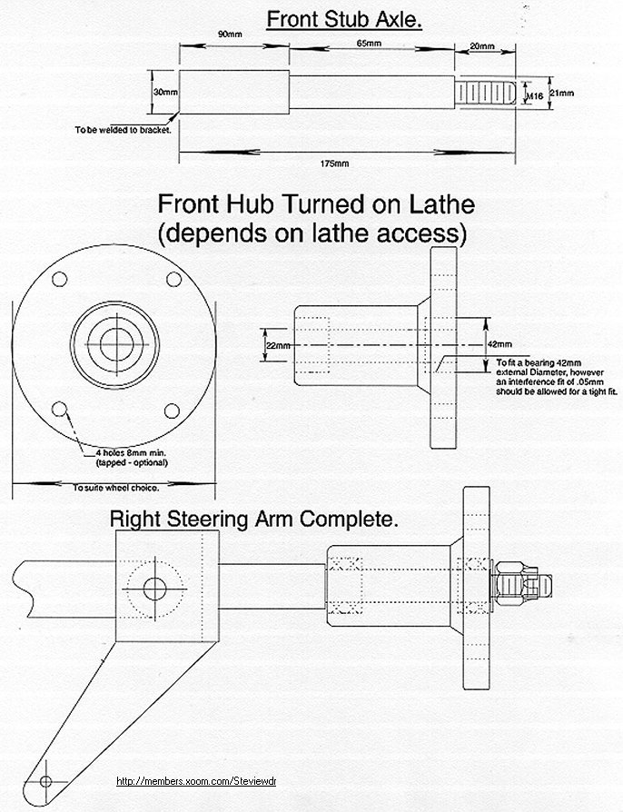
Stub Axles + King Pins.
The following drawings are self explanatory, and should be easy to follow.
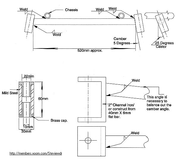
One point to note is the Camber and Castor angles stated, 5 and 25 degrees respectively. The Camber angle is to aid turning corners, especially with the fixed rear axle. The Castor angle is used to turn and keep the wheels pointing forward whenever the steering wheel is let go!. It to also aids turning corners. The angles are to be kept as close to this as possible, different angles are used for different surfaces, tarmac, concrete. The angles stated are an average of all, so this kart will be as effective on most surfaces, grass, clay, etc.
Brass caps/bushings should be fashioned and pressed/hammered into the 30 X 60mm mild steel pipe, nylon can also be used, however brass will take more punishment. The mild steel pipe (30X60mm) is welded to the cross member from the chassis, You will have to be PATIENT here in getting the correct angles. You will have to spot the pipe section onto the member, then adjust the angles so that is makes 5degrees (the top of the pipe pointing inwards) and 25 degrees (the top of the pipe pointing towards the back wheels). As in the diagram. The main thing is to try and have the angles the same for both sides. YOU WILL NOT GET IT RIGHT FIRST TIME SO TRY AND TRY AGAIN, PATIENTLY.
Also to be fashioned is the U bracket, on to which is welded the stub axle. It can either be bent into shape from a 40X6mm flat mild steel bar, or as I done, you can cut a section of 2" channel iron, in such case the measurements may have to be altered. It saved an awful lot of hammering, heating and bending of that 6mm flat bar.
The King Pins are M10mm HTS 8.8 (high tensile steel) bolts, with a lock nut and washer, these run through the U bracket and the hub pivot bushes which are pressed into the chassis pivots.
Make sure you Weld all items exceptionally well, weld a ring once, grind down, clear off the slag, and make another pass. Make sure you get all the way around, and that there are no pits, holes, cracks, etc.
This next drawing shows the steering arm, it's angles, sizes etc.
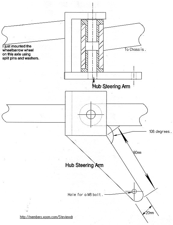
The angle of 108 degrees is part of the "Ackerman angle". with the wheels pointing forward these steering arm angles should come meet and come together in the middle of the rear axle. This principle causes the wheels to be able to turn independent angles, causing the inside wheel to take a sharper angle. This however is all worked out in advance for you.
Another point to note, is the mounting of the front wheels onto the stub axles. The way I have it on my kart at the moment is very crude. All I have done is secured the wheelbarrow hub with it's brass bushing between split pins and washers on the stub axle. I am currently thinking of a better method as the speed goes up and over 50mph the front wheels take on a small wobble!!. However if you have access to a lathe and the appropriate materials you can turn out stub axles and hubs. Here are the plans anyways for those of you who have a lathe.
As you can see from the drawing, it takes a bit of lathe work, including the threading of the last 20mm to take a M16 HTS nut and washer. Also interference fits must be taken into account when pressing the bearings into the hub. But when it is constructed it will be the perfect set-up, and will last forever. Appropriate bearings must be obtained from your local engineering store to fit the 21mm part of the axle, and to fit the internal part of the hub. The nut I recommend is a M16 castle finish nut, requiring a pin to be slotted through the axle. This will keep the nut stationary for good!. Again the external diameter of the hub and the hole alignment will all depend on the size of the wheel.