|
|
 < Back << Kartbuilding Home
Below are the next 3 drawings from the total of 21 in this complete set of Kart Plans focusing on the chassis design.
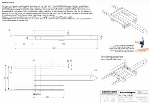
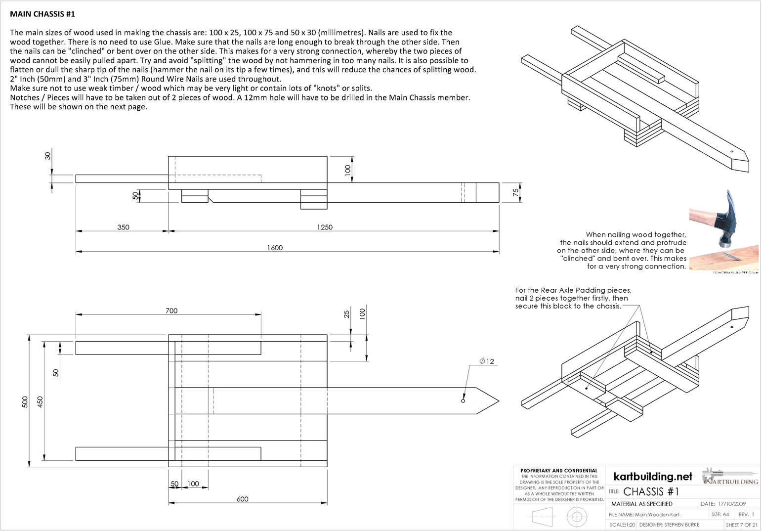
This Drawing shows the complete assembled Chassis. Overall measurements are provided. The pieces of timber are nailed together using round wire nails. Where nails protrude/stick out, they need to be "clinched" (bent over) as this will make for a much stronger connection. Wood screws could also be used, however it would take longer to screw all the parts together as opposed to nailing everything.
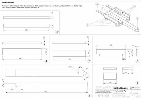
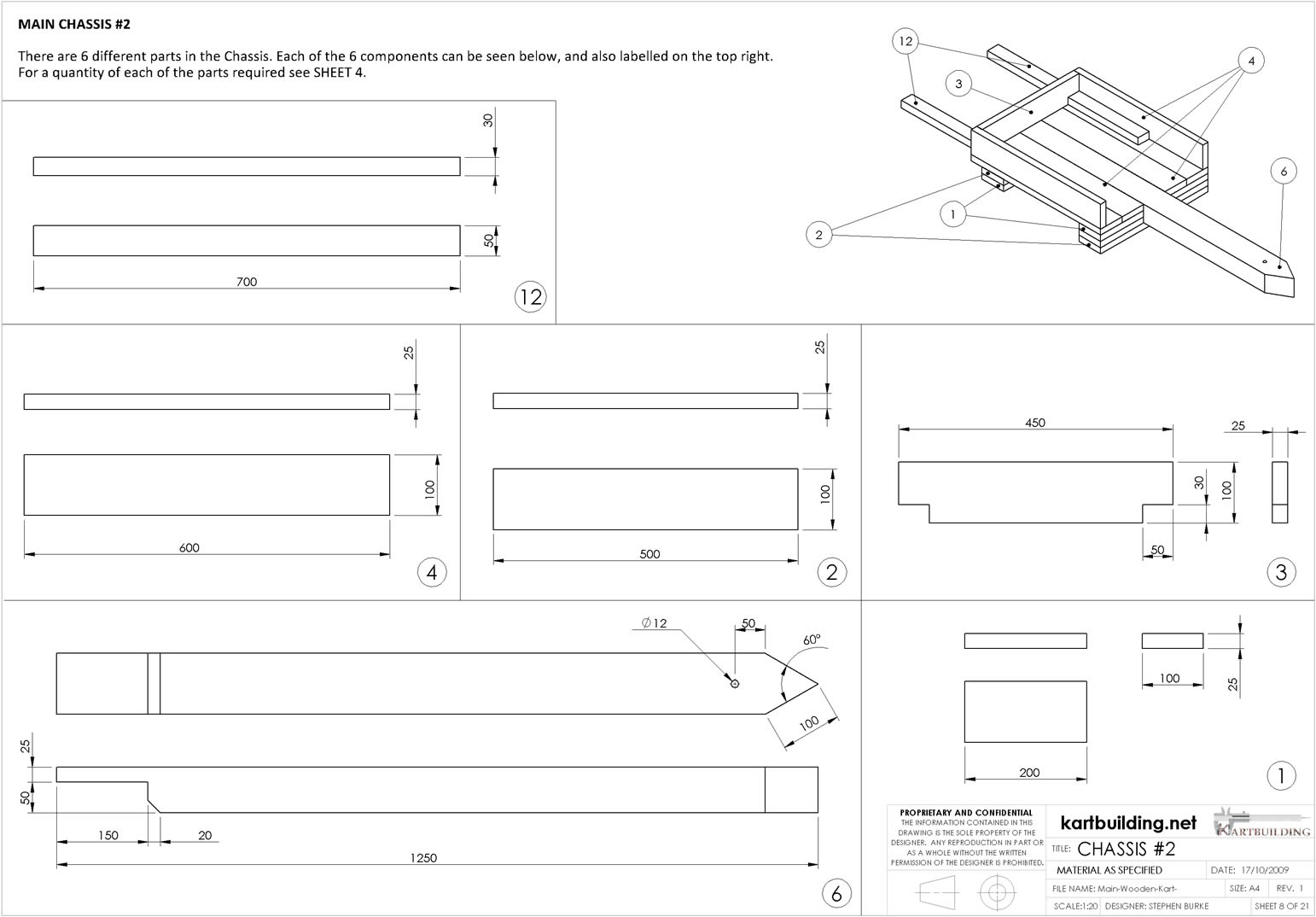
Drawing 8 shows each of the parts required for the Chassis. All sizes and dimensions required to make each of the pieces are shown. As mentioned previously, if you have obtained different sizes of timber, then make the necessary changes so that parts line up correctly. If similar sized timber to these plans cannot be obtained, try and obtain the same width and thickness timber throughout the chassis, as this will make things much easier trying to line up joints and boards.
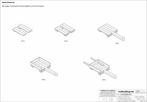
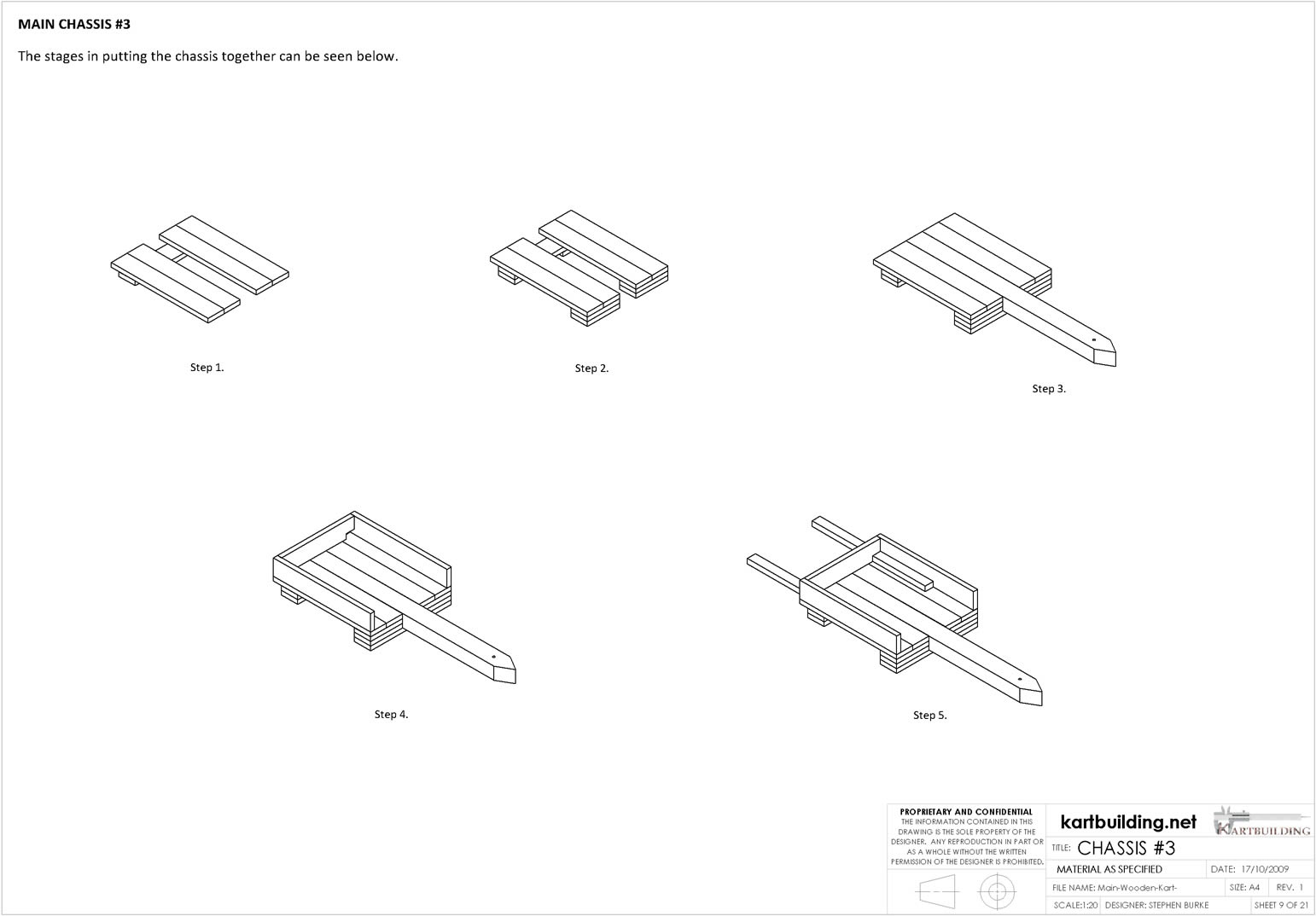
This drawing shows how the chassis should be made in a "Step by Step" approach. By following this approach, it will be easier to nail and secure the pieces of wood together.