The Brakes and Sprocket mountings.
This is now the time to become well aquainted with your local motorcycle
supplier/repair agent as a lot of second hand parts from motorbikes will be
needed, such as the brake, low cost quality sprockets and chains.
I will talk fistly about the Brakes of this kart.
Basically there are two types of brakes 1: Drum Brakes and 2: Disc Brakes.
The latter been the most effective, nevertheless when the Drum brake is setup
correctly is can be better than a poor setup of Disc brakes. The brakes that you
will use on your kart will depend on the amount of money you are willing to
spend. I' m using Drum brakes on my kart at the moment, they only cost me £10
from the rear brake of a honda 90, compared to around £40-50 for a front disc
and calliper of a motorbike. And if you ever drove my kart in the rain you will
realise how gentle you have to be on the drum brake pedal, otherwise the whole
rear will lock up and you will spin off doing 180's. In my opinion drums are
easier and much cheaper, nevertheless I have provided plans for both options, so
well in good if you happen to come across a disc and calliper of a motorbike.
Drum Brakes.
This type of braking method has disadvantages however, and the use of a lathe is
almost a must, even if is it to get it done in a local engineering firm, it's
only a small bit to be turned out as you will see.Firstly you will need the rear
brake from a motorbike, preferably 75cc or higher. The front brake is useless as
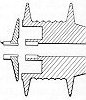
it has no mounting/securing arm to stop the brake plate from rotating. 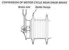 Cut away all the spokes and remove the sprocket and cush drive, then bolt a
plate to this side. (right side on the picture to the left) When the brake is
finally setup and all the diameters all matched up all on has to do is to spot
this plate to the axle. Refer to the picture below of the positioning of the
brake. Only weld up when EVERYTHING is all finished, the shoes working
correctly, as when this steel plate is spot welded to the axle one must grind
off the weld to remove the brake. A bit crude I must admit, but if you want to
go to the bother of making a keyway in the axle and then tapping the fixing
plate to the axle, go ahead.
Cut away all the spokes and remove the sprocket and cush drive, then bolt a
plate to this side. (right side on the picture to the left) When the brake is
finally setup and all the diameters all matched up all on has to do is to spot
this plate to the axle. Refer to the picture below of the positioning of the
brake. Only weld up when EVERYTHING is all finished, the shoes working
correctly, as when this steel plate is spot welded to the axle one must grind
off the weld to remove the brake. A bit crude I must admit, but if you want to
go to the bother of making a keyway in the axle and then tapping the fixing
plate to the axle, go ahead.
The bigger the bike it comes from the better as the internal diameter
will be bigger, and will fit your axle better. When you obtain the drum and
shoes, concentrate firstly on the open drum. Take out the bearing if there is
anyone. Measure the internal diameter. If this measurement is smaller than your
axle then unfortunately the difference must be taken from the drum on a Lathe.
But the internal diameter may be too big!, in this case you will have to hunt
down a pipe to use as bushing, you can weld to, which will take up the
difference between the axle and the drum. If it is too small you will need a
lathe. But not all Lathes have an internal cutting tool, and a drill bit of 30mm
- I have never seen. In this case, your axle will need a bit of lathe work ie.-
taking down. ( If this is too much Lathe work to handle, then stick with the
straight forward Disc Brake)
On the left side of this picture (to the left) you can see the piece to which
the shoes are attached, and this is stationary with respect to the live axle and
drum(to the right of the picture).
See the picture below, the positioning of the brake, and the possibility of
taking the axle down to the required diameter to that point.
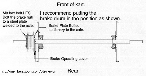
The drum is positioned between the wheel and the frame of the chassis on the
left hand side, with the Shoes part of the Brake (brake plate) on the chassis
side.(this is to provide easy access to secure the shoes to the chassis via the
fixing arm) However depending on your ability and adventureness you could decide
to put the whole brake setup inside the chassis frame. Now moving onto the shoes
part of the brake (brake plate), this is a round cast piece which the brake
pads/shoes are fixed to, and the shoes can be moved outwards by an operating
lever on the outside of this piece, which can be simply connected to a brake
cable. This brake plate is the most difficult piece of the brake system. It is
usually this part which it's internal diameter is too small to fit the axle.
This is where undoubtbly you WILL have to increase the diameter of the shoes
piece on a lathe. Depending on the type of Drum you have you may only be able to
increase the internal diameter a few mill, anymore and you will weaken the
piece. In this case you will have to take the axle down to meet the slightly
bigger internal diameter of the brake plate. You will understand this much
better when you have the brake infront of you. If you can spare 3-4mm then
a brass/nylon bushing could be inserted, so that the brake plate can rotate
smoothly on the axle. If not then the brake plate and the axle must be
thouroughly greesed, with an application of oil every 1-2 weeks.
As you can also see in the picture, that the brake plate that the shoes are
mounted to is kept stationary via a fixing arm which is bolted to the chasssis.
The Drum which is fixed to the rotating axle spins with respect to the brake
plate. Make sure this fixing arm is rigidly fixed with high tensile bolts to the
chassis, as all the torsional load of stopping the kart is transferred through
this member to the chassis. The brake operating lever you can see in the picture
can be simply operated from a cable comming from the brake pedal. Simple!. Any
problems, just e-mail me. ( )
)
Disc Brakes
Disc brakes have a few more advantages over the drum ie.- more effective +
straight forward. However the Disc plate MUST be mounted perfectly on the axle -
which means making a hub to mount it, preferably made on a lathe, the Disc can
not have any wobbles AT ALL!, and it also must be concentric on the axle. Aswell
as all this the calliper must be mounted rigidly to the axle. And as I said
earlier all this cost money especially the disc and calliper. In saying this a
nice hydraulic unit of a scooter etc. would be very nice indeed. I would have
used this method only I didn't have any disc brake available cheaply to me.
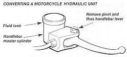
When one thinks about a hydraulic brake they usually think
about pipes and hydraulic fluid. Well that need not be the case. Quite simply
all one has to do is get the whole front unit from a scooter/motorbike, brake
lever and all. Then all one has to do is to mount the brake lever and fluid
reservoir onto a chassis runner close to the rear axle. Then all you must do is
to remove the brake lever, and fashion a small piece of alminium/ mild steel to
fit in it's place. Exactly as it is in the picture below. The two holes is to
provide different leverage pressures. A cable can then be run from this lever to
the brake pedal at the front of the kart. That is the actuating process finished
with. All that's left is to mount the Disc to the rear axle as well as the
callipers. 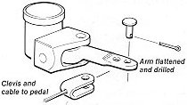
Next you should go onto mounting the plain Disc to the rear axle in the
correct position. The positioning of the calliper can be adjusted to suit the
Disc. To mount the Disc accurately and securely to the axle necessitates
a mounting, something as in the picture below.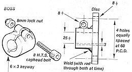
This particular unit is made up of two parts welded togethor, one been a
circular steel plate made from 8mm thick plate, and the other been a section of
bar 45mm in diameter with either a 25 or 30mm internal bore to fit the axle
aswell as a 6x3mm keyway in both the axle and the mounting hub . When this piece
is made a slit of 3-4mm is made with an angle grinder etc. Then an 8mm HTS bolt
is used to pinch/tighten the boss to the axle to prevent side to side movement
on the axle. A grubscrew can also be used to serve this purpose aswell. The two
pieces are then welded togethor on the axle, keeping everything concentric. Also
the correct positions must be made for the Disc it's self, so it too is
concentric. I would mark the positons for the holes to bolt the Disc to the
mounting hub in the lathe. Also I'd advise you to put the whole unit in the
chuck of the lathe to check that the Disc is mounted concentrically aswell as
square to the axle. When this is checked and contains no flaws, then you can
mount it on the axle. Then place the calliper in place and weld if necessary, an
extra runner to the chassis. When this is securely in place test the brake by
spinning the rear wheels in the air, making sure there is no touching of the
calliper and Disc (within a certin limit). Unlike the Sprocket the Disc must be perfectly
square to the axle.
Also when removing the calliper from a motorbike try and prevent the
callipers from falling out, otherwise you will have to drain the hydraulic fluid
from system.
Now moving onto the-
Sprocket for the rear axle.
The sprocket used for this type of kart, should be one from a motorbike.
Bycycle chains come off all the time. The axle diameter will either be 25mm or
30mm.
Method 1.
The most straight forward
method to make a sprocket carrier, is to turn out a steel plate as shown in the
lathe, with and internal diameter of either 25mm/30mm, with a "low
interference fit". Quite simply this plate can be spotted neatly to the
rear axle. This will also allow you a great deal of freedom when aligning the
chain, as this welding is the very last thing to be done prior to driving. 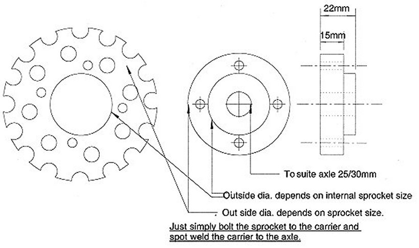
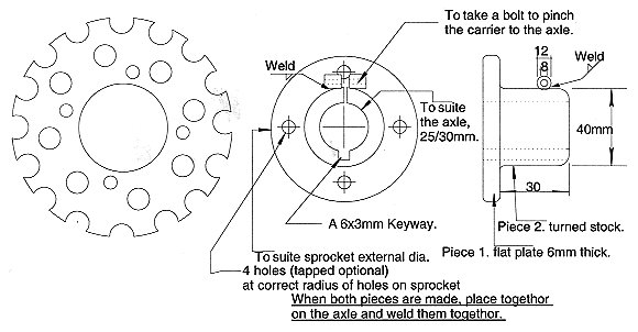
Method 2. This more complicated method of
constructing a "sprocket carrier" is a bit advanced for some people
with limited resources, like myself. It involves constructing in two seperate
halves, then putting both halves on the axle and then to weld them togethor. A
pinch bolt is used to keep the sprocket carrier from moving from side to side on
the keyway. Both the keyway and the pinch sequring method must be used in this
method.
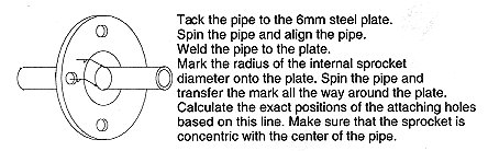
Method 3. The only way I can suggest to
people without "lathe access" is to get a steel pipe (internal dia to
suit the axle), then to get an 6/8mm steel plate, drill out the center (or use a
cutting torch) to fit snugly onto the steel pipe. Spot the plate to the pipe,
spot the pipe to the axle, rotate the axle somehow, and hammer the plate to the
appropiate side untill it wobbles no more!. Weld the plate fully to the pipe.
Mark on the plate the diameter of the four holes from the center of the
sprocket. Now spin the axle again. Hold a sharp point to the plate to where the
point you just marked and with the axle spinning it should make a uniform
circle. Drill the appropiate holes on this circle. This is to keep the sprocket
Concentric to the axle. Bolt up and hopefully! it should be satisfactorly
enough!.
Rember if you have any questions just e-mail me:
Return to Freeplans Homepage