|
|
 < Back << Kartbuilding Home
Below are Drawings 16 and 17 in the set of 21 for this wooden go-kart powered with a small lawnmower engine.
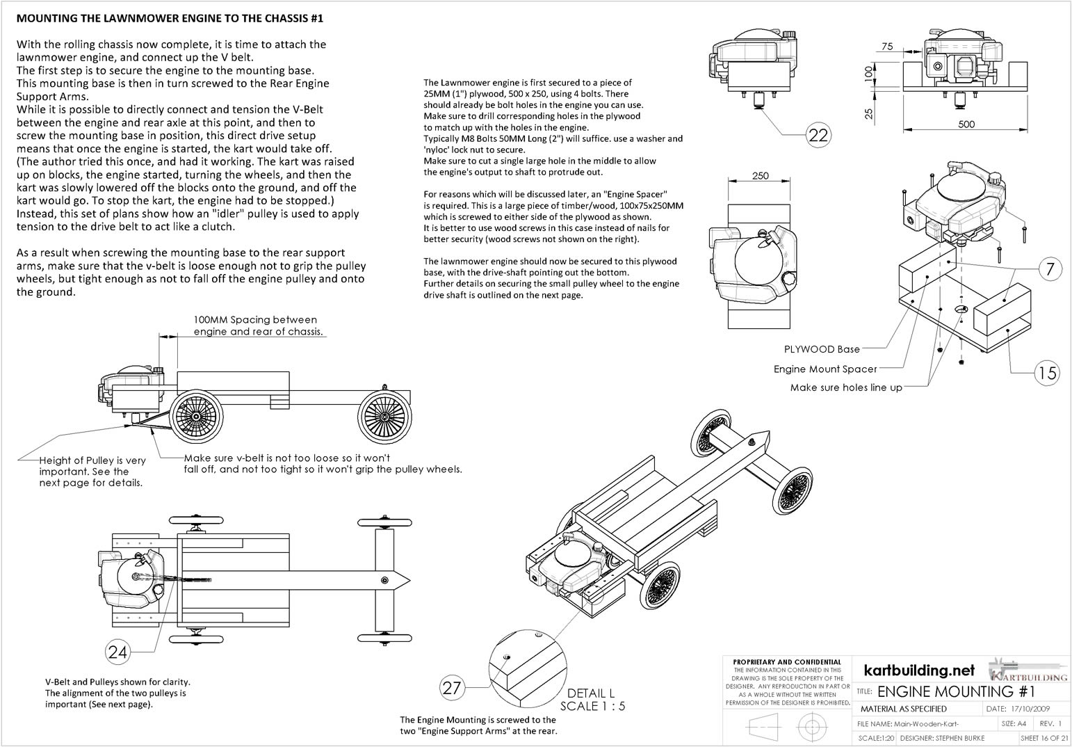
It is very important that the engine is mounted in the correct position. Some people say that drive belts for go-karts are useless, and that that break, slip or come off altogether! If the engine is positioned incorrectly then all of these things will happen!!
It is crucial that the engine is lined up correctly with the rear axle. Begin with bolting the engine to a piece of plywood. Then attach large blocks of timber to either side of the plywood. Make sure to leave at least 100mm between the engine and the back piece of the chassis to allow for fitting the belt tensioner (as will be covered later). Only temporarily screw the engine mount to the chassis, as this will have to be adjusted.
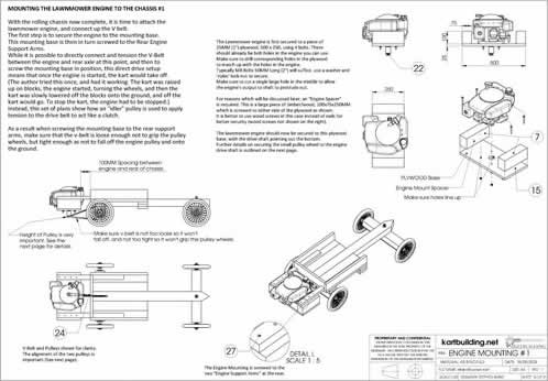
The first step here should be to attach the small V-Belt Pulley wheel to the Engine's output shaft. This can be a little bit tricky to get right. The small pulley wheel needs to be fixed securely to the engines output shaft, and must not slip! The pulley wheel cannot simply be bolted to the output shaft, as this will be insufficient to stop the pulley wheel from spinning. Hopefully the pulley wheel will be thick enough to cut a slot/groove (using a hacksaw and metal file) which will suit and match up with the engines output shaft. The engine and output shaft shown in this drawing is a Briggs and Stratton type lawnmower engine. Things might be different on your engine.
If you are having problems securing the pulley wheel to the engines output shaft, email kartbuilding [at] gmail.com with photos of the output shaft and pulley and the author will suggest some methods and options.
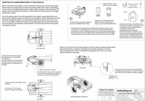
Once the pulley wheel is attached to the engine, the engine needs to be lined up correctly, such that the pulley wheel on the engine and the rear axle line up as much as possible. If necessary the "Engine Mount Spacers" (Part 7) may have to be made smaller/bigger to suit the diameter of the large pulley wheel on the engine.
Once the engine is lined up, insert a number of wood screws fixing the engine mount board to the chassis. Again by using screws this will allow the engine to be moved and its position tweaked later as necessary. Note: Do not tension the V-Belt at this stage. The V-Belt must be loose so the engines output shaft can rotate without gripping the v-belt. The v-belt must not be too loose in case it may fall off.